Autonomous car

Final degree project that includes the electronics of an autonomous vehicle. Done in partnership with another course colleague.
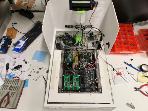
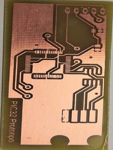
In this project, PCBs were designed and produced to make the electronic part of the vehicle. This being my first contact with PCB design, I can say that I loved it and for that reason I do it with you in my free time.
I would like to share all the schematics, layouts of the PCBs and all the programming, however I fear that it may suffer from ownership issues due to it being made at the university and possibly still being used.
Turn Signal PCB
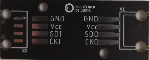
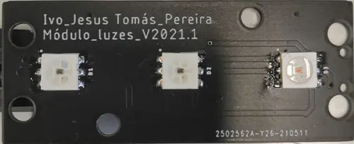
The first PCB to be corrected and produced was the one for the turn signals, I say corrected because it had already been started to be developed the previous year by other colleagues, hence the names of the same. This super simple PCB has only 3 RGB LEDs and the output for communication with them, these allow several to be interconnected and controlled individually.
Turn Signal PCB Controller
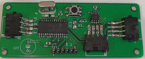
This PCB contains a PIC18F that controls the LEDs on the turn signal PCB via SPI communication. We can see that the soldering is not the best but we were new to that too
Car steering PCB
A PCB with a PIC32 capable of controlling the vehicle’s servo motor in order to control its direction was developed.This PCB allowed the vehicle’s steering to be controlled and adjusted according to the error associated with mechanical steering. These errors and deviations were obtained through experimental tests.
SAMD
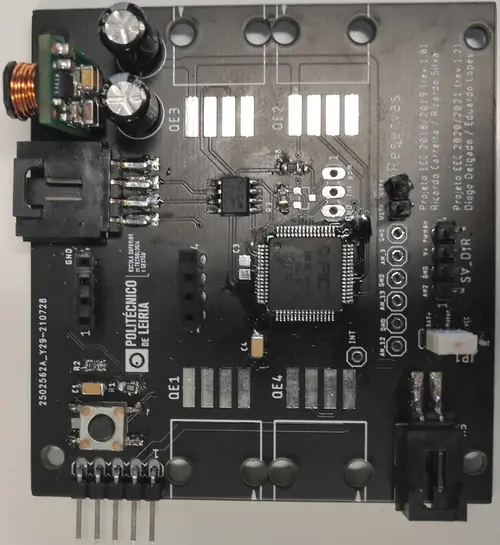
And finally, a PCB was developed capable of powering and communicating with the remaining PCBs. The PCBs communicate with each other via CAN BUS communication.This also had a current and voltage sensor that allows monitoring these values of the battery that powers the car. It also contains support for connecting an OLED display that shows these values.
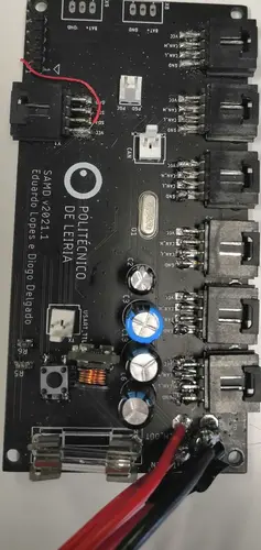
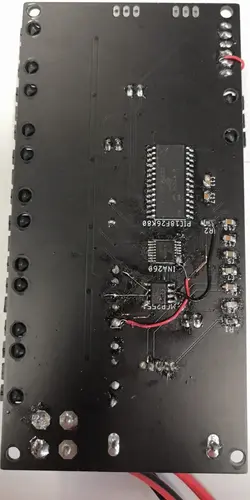
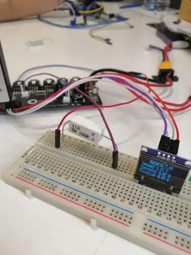
As we can see, not everything was well designed in the software, which is perfectly normal since there was only one opportunity to order PCBs. Therefore, some adjustments had to be made.
Final Car
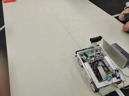
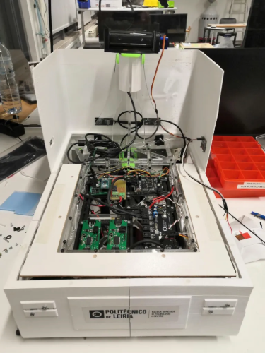
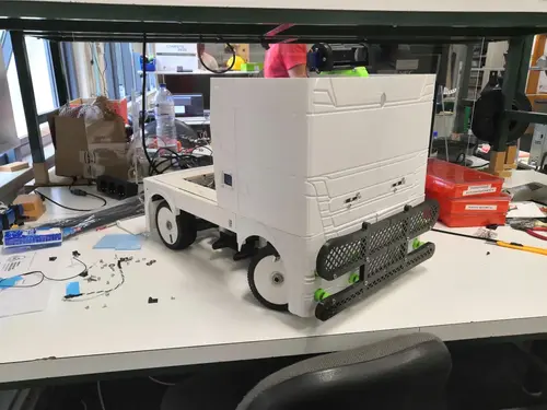
Finally, all the PCBs were connected and mounted to the car chassis.
Other skills acquired
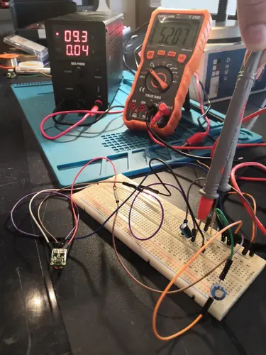
Circuit debug
Several tests and debugging were carried out on the PCBs to check for components that were incorrectly dimensioned, connected, etc. Debugging and monitoring communications (mainly the CAN BUS) was also carried out.
Microcontroller Programming
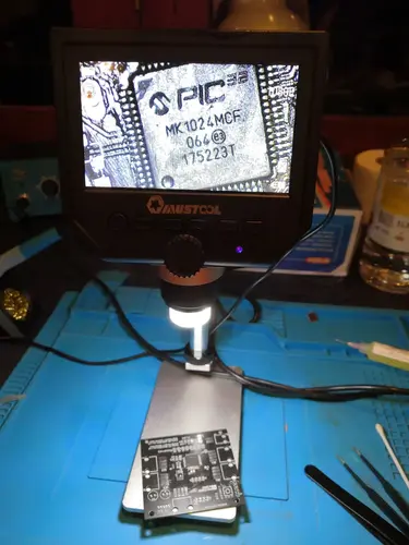
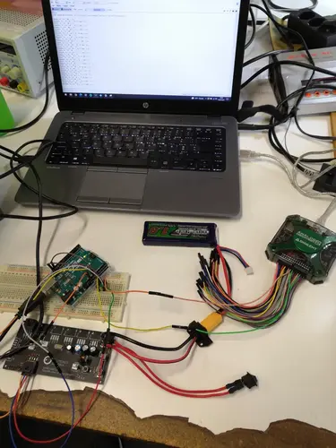
Another skill improved was the programming of microcontrollers, namely the Microchip PIC using the MPLAB software and C programming. Arduino was also used for prototyping and therefore the Arduino IDE was also used.
Prototype and welding
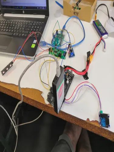
PCB prototypes were also made at the university for testing and the entire manufacturing process was visualized. The ability to solder SMD components was also developed, since all components were soldered “by hand” by us.